
FAST User Guide
Version: FAST Ver.20260530
Full name: Fluent Auto & Setup Turbo
1. Overview
FAST is an automation tool for Ansys Fluent. It reads case configurations from a parameter table in batches, starts Fluent automatically, applies boundary-condition settings, runs iterations, extracts pressure/torque results, and generates Excel result files.
The current version supports three calculation modes:
Mesh: starts from a mesh file (.msh*), creates Fluent settings automatically, and runs batch calculations.Case: starts from an existing Fluent case file (.cas*or.cas.h5*), modifies operating conditions in batches, and runs calculations.Cavitation: starts from an existing Fluent case file, performs automatic step-by-step outlet-pressure reduction, and searches for the point where the head drops by approximately 3%.
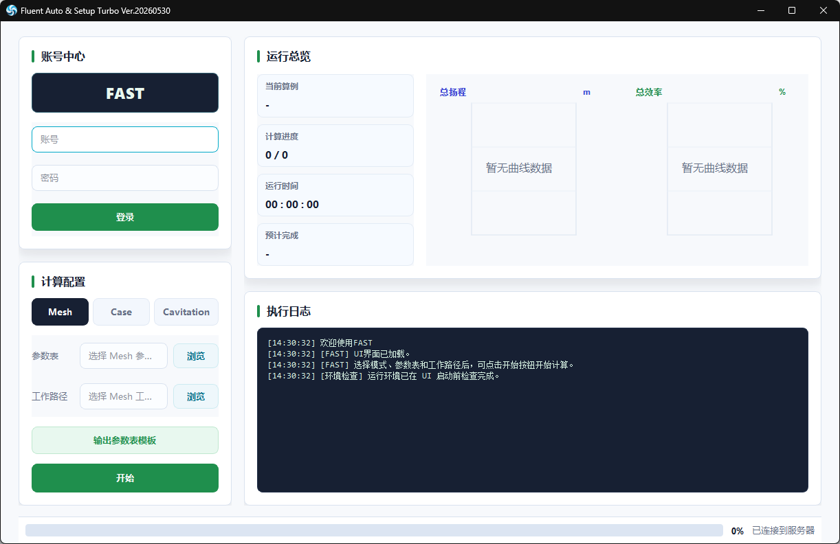
The interface includes account login, mode selection, parameter-table selection, working-directory selection, run overview, real-time curves, and execution logs. Login is not required for local calculation. After login, task status and result files are uploaded to the FAST server.
2. Runtime Environment
2.1 Requirements
- Windows operating system.
- Ansys Fluent installed and able to be launched normally by PyFluent.
- Python 3.11.9 installed, with the
pythoncommand available. For troubleshooting, refer to the Python installation procedure at the end of this document. - To better support network environments in mainland China, FAST uses the Tsinghua PyPI mirror by default:
https://pypi.tuna.tsinghua.edu.cn/simple.
2.2 Python Packages Checked/Installed Automatically
During startup, FAST automatically checks and installs the following dependencies:
PyQt6openpyxlpandasansys-fluent-core==0.35.*protobuf==5.29.6grpcio==1.74.0
The first startup may take some time. Installation logs are written to fast_startup_install.log in the program directory.
2.3 Startup
Recommended startup method:
FAST.exe (for example, FAST20260530.exe)
FAST attempts to check the server for updated code. If the online update check fails, the program continues using the built-in version.
3. Main Interface Workflow
- Open
FAST.exe. - If you need to upload task status and results, enter your account and password in the account area on the left, then click "Login".
- In "Calculation Configuration", select
Mesh,Case, orCavitation. - Click "Export Parameter Table Template" to generate an Excel parameter-table template for the selected mode.
- Fill in the parameter table and save it as an
.xlsxfile. - Click "Browse" next to "Parameter Table" and select the parameter table.
- Click "Browse" next to "Working Directory" and select the folder that contains the mesh or case files.
- Click "Start".
- View the current case, progress, elapsed time, estimated completion time, curves, and logs on the right side.
Using .xlsx parameter tables is recommended. The interface preview logic does not support .xls parameter tables.
4. Working Directory and File Naming Requirements
FAST searches for input files in the selected working directory according to the names in the parameter table.
4.1 Mesh Mode
Use the generated parameter-table template to obtain the dedicated table for Mesh mode.
The Mesh Name value in the parameter table must match the prefix of the mesh file name.
Example:
Parameter table Mesh Name: pump_A
FAST searches for the following file in the working directory: pump_A.msh
or: pump_A.msh.h5
This is the most commonly used FAST mode. It is mainly intended for large numbers of model calculations during the geometry optimization stage. As long as naming is standardized, it can theoretically support many pump configurations.
4.2 Case Mode
The Case Name value in the parameter table must match the prefix of the case file name.
Example:
Parameter table Case Name: pump_A
FAST searches for the following file in the working directory: pump_A.cas
or: pump_A.cas.h5
This mode is mainly used for projects or research cases that require special case settings, such as different media or different temperatures. You can also use Mesh mode with the iteration count set to 1 to automatically generate a case setup, then modify the generated case and continue from it in Case mode.
4.3 Cavitation Mode
The Case Name value in the parameter table must match the prefix of the case file name. FAST searches the working directory for:
CaseName.cas or CaseName.cas.h5
Cavitation mode only requires one case file. FAST automatically configures the Mixture model and Cavitation model, then automatically stops after detecting a 3% head drop.
Cavitation results are written into a subfolder named after Case Name under the working directory.
5. Fluent Model Naming Requirements (Very Important)
FAST relies on Fluent zone and boundary names to automatically identify the inlet, outlet, impeller, torque walls, and interfaces. To ensure the automation workflow runs correctly, the model must follow these naming rules:
- Name the inlet boundary
inlet. - Name the outlet boundary
outlet. - The impeller/rotating fluid zone name must contain
yl. - The impeller torque wall name must contain both
ylandwall. - Boundaries that are not walls, not inlet, not outlet, and not body zones are treated as interfaces.
- Paired interfaces should use inverse naming, such as
a-bandb-a.
If boundary names do not follow these rules, FAST may be unable to create interfaces, set rotational speed, extract total pressure, or calculate torque.
6. Parameter Table
Multiple rotational speeds or operating-condition points can be separated by spaces or English commas. For example:
Speed: 1450, 1750
Operating condition: 0.8 1.0 1.2
Mesh and Case modes calculate each combination of "speed x operating condition".
6.1 Mesh Mode Parameter Table
Headers:
| Column | Description |
|---|---|
| Mesh Name | Prefix of the mesh file name. FAST searches for MeshName.msh*. |
| Speed | Rotational speed, in rpm. Please confirm the sign convention. Multiple values are supported and can be separated by spaces, for example 800 1200 1400. |
| Inlet Outer Diameter | Inlet outer diameter, in mm. |
| Inlet Inner Diameter | Inlet inner diameter, in mm. |
| Outlet Outer Diameter | Outlet outer diameter, in mm. |
| Outlet Inner Diameter | Outlet inner diameter, in mm. |
| Q | Design flow rate or reference flow rate, in m^3/h. |
| Operating Condition | Flow-rate multiplier/operating point. Multiple values can be separated by spaces, for example 0.8 1.0 1.2. Actual flow rate = Q x Operating Condition. |
| Iteration Steps | Number of Fluent iterations for each operating condition. |
| Cores | Number of processor cores used when Fluent starts. |
| Scale Mesh | Enter 1 if the mesh was created in millimeters using ICEM. Enter 0 for ICEM meter meshes and Fluent Meshing meshes. |
Main operations in Mesh mode:
- Start the 3D Fluent Solver.
- Read the
.msh*mesh. - Optionally scale the mesh.
- Set 25 degrees Celsius clean water as the fluid material.
- Set the
k-epsilonturbulence model. - Calculate inlet velocity based on inlet area and
Q x Operating Condition. - Set the MRF angular velocity of the impeller zone according to speed.
- Create interfaces automatically.
- Save case-data after each operating condition.
- Extract total pressure at inlet/outlet/internal boundaries and torque on impeller walls.
- Generate the result Excel file.
6.2 Case Mode Parameter Table
Headers:
| Column | Description |
|---|---|
| Case Name | Prefix of the case file name. FAST searches for CaseName.cas*. |
| Speed | Rotational speed, in rpm. Please confirm the sign convention. Multiple values are supported and can be separated by spaces, for example 800 1200 1400. |
| Inlet Outer Diameter | Inlet outer diameter, in mm. |
| Inlet Inner Diameter | Inlet inner diameter, in mm. |
| Q | Design flow rate or reference flow rate, in m^3/h. |
| Operating Condition | Flow-rate multiplier/operating point. Multiple values can be separated by spaces, for example 0.8 1.0 1.2. Actual flow rate = Q x Operating Condition. |
| Medium Density | Fluid density, in kg/m^3. |
| Iteration Steps | Number of Fluent iterations for each operating condition. |
| Cores | Number of processor cores used when Fluent starts. |
Main operations in Case mode:
- Start the 3D Fluent Solver.
- Read an existing
.cas*or.cas.h5*file. - Calculate inlet velocity based on inlet area and
Q x Operating Condition. - Set the MRF angular velocity of the impeller zone according to speed.
- Initialize and iterate for each operating condition.
- Save case-data for each operating condition.
- Extract total pressure and torque.
- Generate the result Excel file.
6.3 Cavitation Mode Parameter Table
Headers:
| Column | Description |
|---|---|
| Case Name | Prefix of the case file name. FAST searches for CaseName.cas*. |
| Inlet Outer Diameter | Inlet outer diameter, in mm. |
| Inlet Inner Diameter | Inlet inner diameter, in mm. |
| Flow Rate | Actual flow rate, in m^3/h. |
| Speed | Rotational speed, in rpm. Cavitation mode does not support variable speed. |
| Pressure Reduction Step | Outlet pressure reduction step, in Pa. Default: 10000 if left empty. |
| Medium Density | Fluid density, in kg/m^3. |
| Saturated Vapor Pressure | Saturated vapor pressure, in Pa. Default: 3540 if left empty. |
| Iteration Steps | Number of Fluent iterations for each pressure point. |
| Cores | Number of processor cores used when Fluent starts. |
Main operations in Cavitation mode:
- Start the 3D Fluent Solver.
- Read the existing case file.
- First run a single-phase baseline calculation and extract the inlet/outlet total-pressure difference.
- Set the initial outlet pressure to approximately
1.3 x baseline total-pressure differenceas a safety margin, then round it upward. - Switch to the Mixture multiphase model and enable cavitation mass transfer.
- Gradually reduce outlet pressure. For each pressure point, iterate and extract inlet/outlet static pressure and total pressure.
- Calculate head, head-drop ratio, total NPSH,
v2/2g, and cavitation specific speed. - When the head-drop ratio reaches or exceeds 3%, mark the previous pressure point as the "cavitation point".
- After reaching 3%, continue calculating two additional pressure points.
- Try up to 100 pressure-reduction points.
7. Result Files
7.1 Common Output
The run log is written to the working directory:
run_log.txt
The right side of the interface also displays execution logs in real time.
7.2 Mesh/Case Results
The result Excel file is written to the working directory. The file name is usually:
InputFileBaseName.xlsx
Common result columns include:
SpeedAngular VelocityQdFlow RateTotal HeadTotal Shaft PowerTotal Efficiency- Head of each impeller
- Shaft power of each impeller
- Efficiency of each impeller
- Torque of each torque wall
- Total pressure of each boundary
Notes:
Qdis the operating-condition value in the parameter table.Flow Rate = Q x Qd.Angular Velocity = 0.1047198 x Speed rpm.
7.3 Cavitation Results
Each cavitation case creates a subfolder under the working directory. The result Excel file is usually:
CaseFileBaseName_cavitation.xlsx
Common result columns include:
Flow RateInlet Outer DiameterInlet Inner DiameterSpeedInlet Static PressureOutlet Static PressureInlet Total PressureOutlet Total PressureTotal HeadHead Drop RatioTotal NPSHv2/2gCavitation Specific SpeedRemarks
When FAST identifies the cavitation point, it writes "Cavitation Point" in the Remarks column.
8. Interface Curves
Mesh and Case modes:
- The left curve shows
Total Head. - The right curve shows
Total Efficiency. - The horizontal axis uses the
Qdoperating-condition value.
Cavitation mode:
- The left curve shows
Total Head. - The right curve shows
Head Drop Ratio. - The horizontal axis uses outlet static pressure.
9. Account and Online Features
FAST accesses the Fast on Cloud service under:
https://blog.superdarwin.cn/
After successful login, FAST will:
- Register the task list.
- Maintain connection status.
- Update task runtime status.
- Upload basic information, table contents, and file contents of result Excel files.
If you do not log in, or if the network is unavailable, local calculation can still continue, but remote status and results will not be uploaded.
10. FAQ
10.1 Startup Is Slow
During the first startup, FAST checks and installs Python dependencies. This is normal. Check:
fast_startup_install.log
10.2 Python Cannot Be Found
The packaged FAST.exe still needs to call the system Python to run the interface and calculation code. Install Python 3.11.9 provided on the website's Sources page, and make sure the python command is available.
10.3 Parameter Table Parsing Failed
Check the following first:
- Make sure the parameter table is closed. If it is open in another program, FAST may be unable to read it.
- Make sure the parameter table is
.xlsx. - Make sure the headers exactly match the template.
- Make sure the
Operating Conditioncolumn exists. - Check whether blank rows, merged cells, or hidden characters affect reading.
10.4 Mesh or Case File Cannot Be Found
Check whether the name in the parameter table matches the file name:
- Mesh:
Mesh Namecorresponds toMeshName.msh*. - Case/Cavitation:
Case Namecorresponds toCaseName.cas*.
Do not place the input file only inside a subfolder of the working directory. FAST mainly searches directly in the selected working directory.
10.5 Fluent Failed to Start
Check:
- Whether Ansys Fluent is fully installed.
- Whether the current Python environment can import
ansys.fluent.core. - Whether
ansys-fluent-coreis0.35.*. - Whether the
Coresvalue in the parameter table exceeds the available CPU cores on the machine.
10.6 Abnormal Total Pressure, Torque, or Efficiency Results
First check the naming in Fluent:
- Whether
inletandoutletexist. - Whether the impeller zone contains
yl. - Whether the impeller torque wall contains both
ylandwall. - Whether interfaces can be matched as pairs.
10.7 Cavitation Does Not Reach 3% Head Drop
FAST calculates up to 100 pressure-reduction points by default. If the 3% head drop is still not reached after the limit, FAST outputs a warning and uses the last pressure point as the returned result. You can try increasing the pressure reduction step or checking the initial case setup.
11. Recommendations
- Prepare a clean working directory before each run, and avoid Chinese characters in the path.
- Use only letters, numbers, underscores, and hyphens in parameter-table, mesh, and case file names whenever possible.
- Test naming, boundary recognition, and result output with a small number of operating conditions before running large batches.
- Do not manually delete temporary
.txt,.xlsx, or case-data files generated by FAST during operation. - For long batch calculations, keep the network and power supply stable.
12. Result Reference
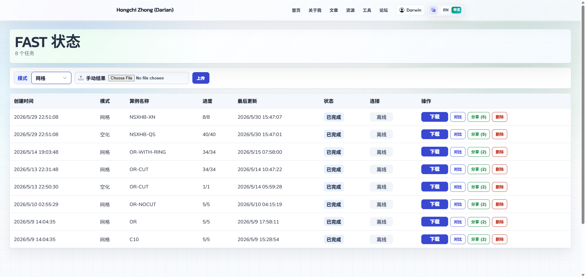
All calculation results are uploaded to the logged-in FAST account, where they can be downloaded and optionally shared with other users for viewing.
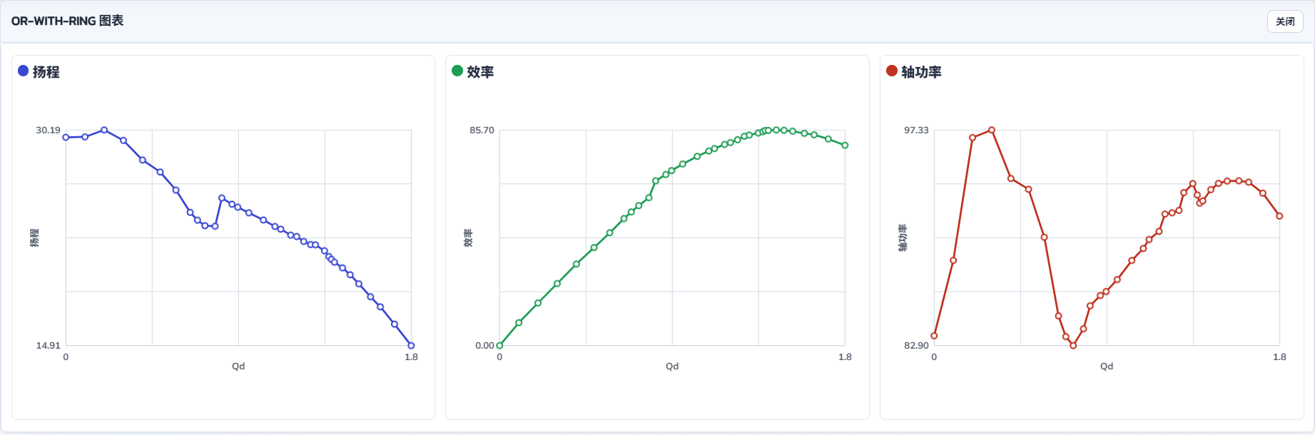
Click a case result to draw and view head, efficiency, and shaft-power curves.
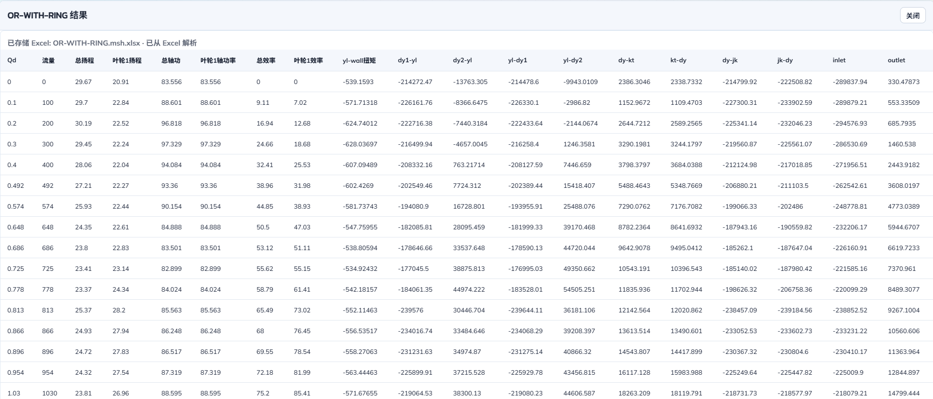
All raw results are displayed below the three curve charts.
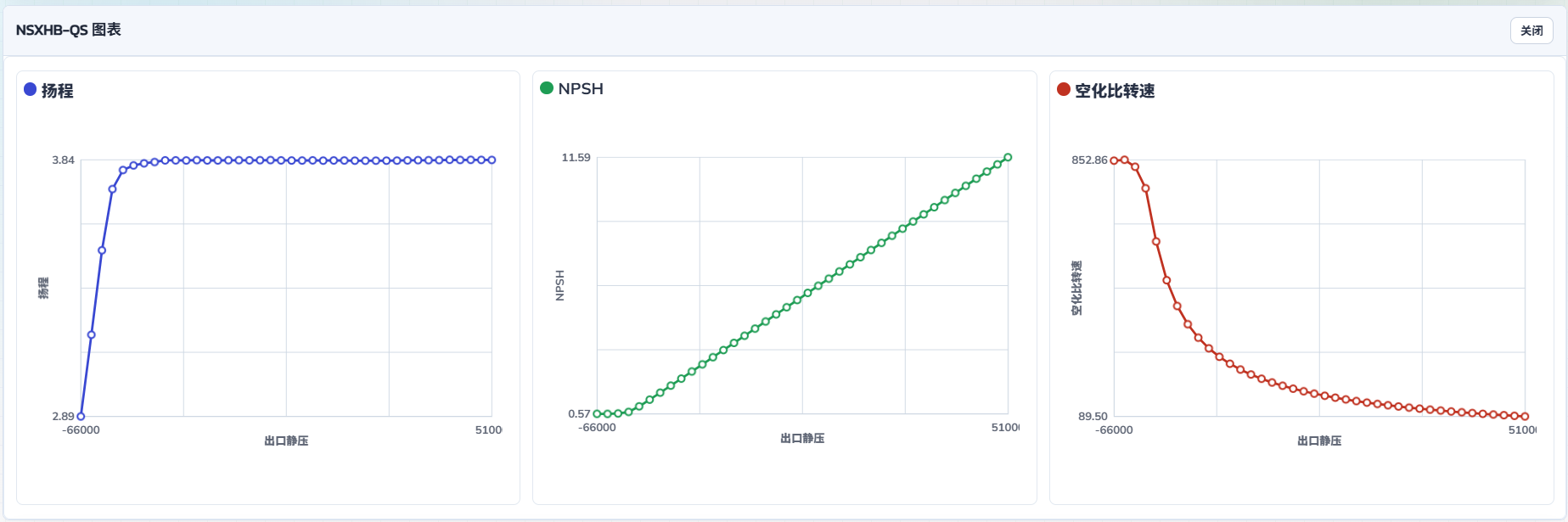
Cavitation mode calculation result display.
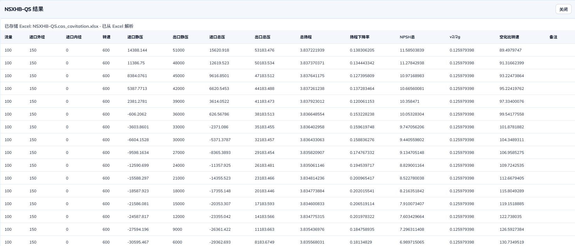
Cavitation mode raw result display.
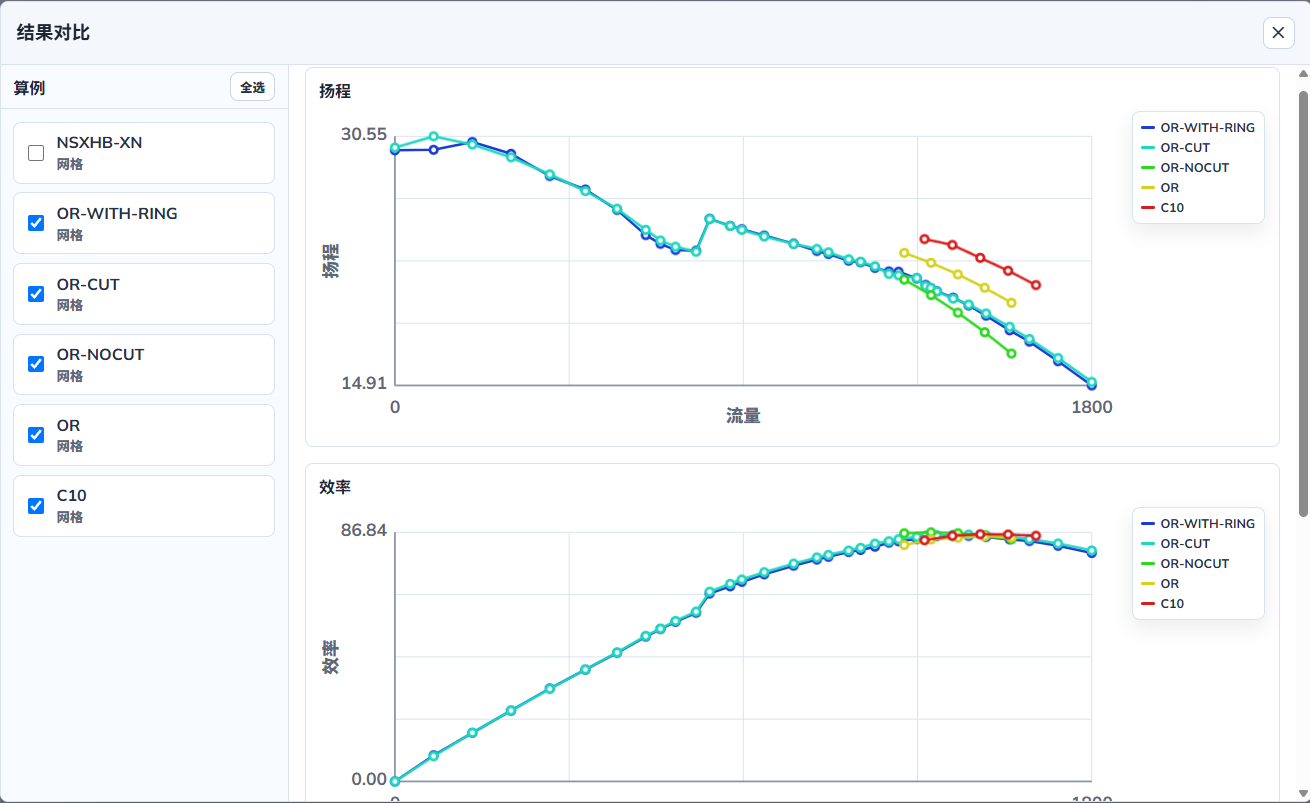
In the comparison feature, different designs of the same model can be selected for comparison, making it easier to choose the better solution. Note: Cavitation mode cannot be compared with Mesh or Case mode. Mesh mode and Case mode can be compared with each other.